
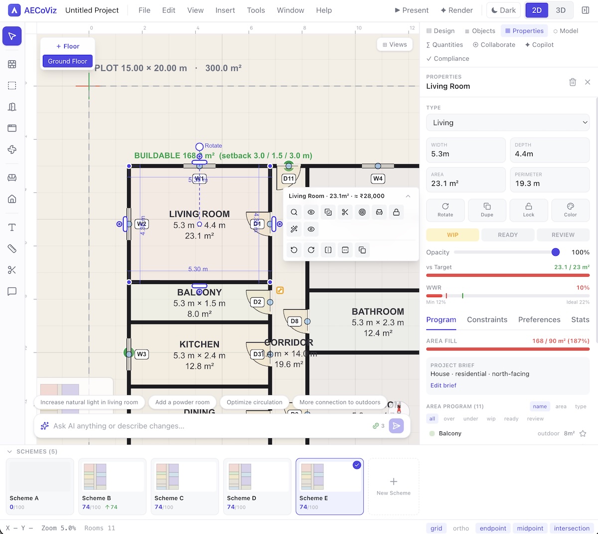
Floor Plan Studio is an AI floor plan generator that turns a room program into ranked, editable layout schemes — not a rendered image, but real wall/room/door/window geometry you keep refining afterward. Start from your plot dimensions, setbacks and building type; a deterministic layout solver (a guillotine slicing-tree algorithm) and an AI variant strategy each propose distinct schemes, scored on area efficiency, adjacency and compliance, with a deterministic fallback so generation never depends entirely on an external AI provider being available. From there it works like a precision 2D/3D CAD tool: snap walls to a grid, ortho or polar axis, split rooms with true topology (a wall carries and updates both sides when you move it), place doors and windows with correct plan symbols, and switch to a live-linked 3D view at any time.
What it helps you do
- Start from plot, setbacks and building type
- Generate room programs and alternate schemes
- Edit rooms, walls, openings, furniture and dimensions
- Review compliance, areas and quantities before export
AI room programs
Create editable programs from project parameters, then tune spaces before generating schemes.
CAD-grade editing
Move rooms, snap walls, split spaces, manage openings and work in 2D or 3D.
Architectural dimensions
Subtle plan-style dimensions, resize handles and guides stay readable while you edit.
Design intelligence
Compliance checks, BOQ, wall issues and plan cleanup tools stay close to the canvas.
Modify tools
Move, copy, rotate, mirror, offset, rectangular/polar array and trim/extend — the same operations you'd expect from a CAD package.
Snapping engine
Grid, ortho, polar and endpoint/midpoint/intersection/perpendicular/nearest object snaps, so walls meet cleanly without manual nudging.
Everything included
Compliance and Vastu analysis
Every plan is checked live against a data-driven ruleset — Generic or NBC-India, selectable by region, with Vastu toggleable separately. It covers byelaw checks (FAR, ground coverage, setbacks, minimum room areas, ventilation, parking), egress (reachability, exit width, travel distance) and accessibility (door clearance, wheelchair turning circles) — each pass/warn/fail with the offending geometry highlighted directly on the canvas. A live FAR/coverage/footprint/carpet calculator and a circulation space-efficiency heatmap update as the plan changes, alongside a compliance report PDF carrying the mandatory advisory disclaimer.
Quantities, cost and sustainability
A quantity takeoff (BOQ) is derived directly from the geometry — wall masonry, plaster and paint, floor and ceiling finishes, RCC slab volume, door and window counts — priced against an editable regional rate library (INR/USD). Alongside it: a RERA-style area statement (carpet, built-up and super-built-up with loading), an indicative embodied-carbon estimate, and a one-click .xlsx export with one sheet per section, all figures clearly labelled indicative rather than a quote.
AI design copilot
A chat interface turns plain-language instructions — "make the kitchen bigger", "add a window to the bedroom", "rename X to Y" — into a small set of typed, validated operations, never freeform coordinates, applied through the normal undo/redo stack. A separate critique mode returns geometry-linked notes (code risks flagged via the compliance engine, dead-corner percentage, poor proportions), and a narrative generator drafts client-facing prose describing the scheme. Imported DXF underlays can be auto-cleaned (snapped, squared, de-duplicated) the same way.
Advanced generative design
A multi-objective optimizer generates several candidate layouts across varied solver strategies and ranks them by a chosen objective — area efficiency, daylight, circulation or cost — with per-objective score bars so you can see the trade-off, not just a single "best" answer. Multi-floor stacking replicates the ground plate across additional floors with a vertically-aligned stair core; a land-layout planner subdivides a larger parcel into plots and a spine road with yield metrics; a sun/shadow study drives real-time shadow casting from azimuth/altitude sliders in the 3D view.
Modeling and construction detail
Composite wall types (brick, block, partition, insulated cavity, stud — a layered assembly library) apply per-wall with the masonry BOQ computed from the structural layer. Stairs are generated code-correct (riser ≤ 190mm, tread ≥ 250mm, the 2R+T comfort rule, risers auto-derived from floor-to-floor height) with a plan symbol and UP arrow. Pitched, gable and flat roofs generate over the footprint in 3D; curved walls bow into a faceted arc with arc length reflected in the quantities; a structural grid lays out columns, and site elements (trees, parking, paving, driveways) round out the plot.
Sketch capture and onboarding
A no-key, in-browser auto-trace turns an uploaded sketch or photo into editable wall geometry plus a trace-over underlay — no vision-model API key required, output clearly labelled a rough estimate. An underlay scale calibrator rescales an imported image by drawing one line of known real length; custom .gltf/.glb assets persist on the project and appear in the insert palette; and studio/2BHK/office project templates give new projects a real starting point instead of a blank canvas.
Collaboration and client review
Pinned comments with threads and resolve, plus box markups directly on the plan, keep design feedback attached to the geometry it's about. View-only share links open a public presentation mode that collects structured feedback with no login required. Version history is built on the native .fpsx format's own snapshots (snapshot, restore, delete, visual diff), and teams/workspaces support members with owner/editor/viewer roles per project — plus a client-ready brochure PDF (cover, plan and area statement) when it's time to hand something off.
Who it's for
- Architects who want a starting layout in seconds instead of a blank canvas
- Interior designers refining room adjacencies and furniture placement
- Builders and developers checking FAR, coverage and setback compliance before committing to a plan
- Homeowners exploring a 2/3BHK layout before briefing an architect
Export and output formats
- Native .fpsx project (lossless, re-editable)
- DXF (layer-preserving)
- SVG
- PDF plan sheets with title block, scale and north arrow
- glTF / OBJ (3D)
- PNG snapshot
- JSON
AI generation vs. drafting from scratch in CAD
A blank CAD file starts every project at zero — walls, rooms and code checks all have to be built up by hand before you can judge whether a layout even works. Floor Plan Studio's generator turns a room program into a scored set of alternate schemes in seconds, each one real editable wall/room/door/window geometry (not an image to trace over). You still do the design work — refining adjacencies, proportions and material choices is what takes judgment — but you start from a buildable layout instead of an empty grid, and compliance/area checks run live as you edit rather than as a final manual pass.
Frequently asked questions
Is the AI-generated plan ready to build from?
No — treat it as a strong starting layout, not a final construction document. It's real, dimensioned geometry (not a rendered image), so you can immediately start refining it, but a licensed architect or structural engineer still needs to review and sign off before construction.
What building codes does it check against?
The compliance engine ships with a generic ruleset and one modeled on India's National Building Code 2016 (FAR, ground coverage, setbacks, minimum room areas, ventilation, parking, egress, accessibility). Local byelaws vary by jurisdiction and change over time — always verify against your local authority's current regulations before submitting or constructing.
Can I import an existing plan instead of generating one?
Yes — import a DXF as editable walls, or trace over an imported DXF/image underlay. There's also a sketch/photo-to-walls capture tool for starting from a hand sketch.
What file formats can I export?
DXF, SVG, PDF plan sheets (with a title block, scale and north arrow), glTF/OBJ for 3D, a PNG snapshot, JSON, and the native .fpsx project format, which round-trips losslessly. DWG and IFC import/export are scaffolded but depend on a licensed external converter, not shipped standalone.
Does it work in 3D, not just 2D plan view?
Yes — every plan has a linked 3D view (walls extruded with real openings, orbit and first-person walk cameras), and edits in one view are reflected in the other immediately.
Is there a cost estimate, not just the floor plan?
Yes — a quantity takeoff (walls, finishes, RCC slab, door/window counts) and an indicative cost estimate against an editable regional rate library, clearly labelled as indicative, not a quote.
Can it generate construction documents, not just a plan?
Yes — auto-generated sections (cut along a section line) and elevations (per facade) stay live-linked to the model, alongside door/window schedules and a room/area statement derived from the same data. A drawing-sheet composer (title block, sheet numbering, scale, revision table) batch-exports a multi-page PDF set, one page per sheet.
Can I design a multi-storey building, not just one floor?
Yes — multi-floor stacking replicates the ground plate across additional floors at stacked elevations with a vertically-aligned stair core, and a floor switcher lets you move between levels while editing.